These drawings are made using AutoCAD, and they were a basic start to CAD. These drawing included a lot of pictorials: were the object was made looking at it from three different views the top, front, and right side. The allow to for the viewer to see the hidden lines and to see the dimension of how the objects are built. The hardest part about these drawing was the dimensioning because there are very specific dimensioning rules, and if you were not careful you could repeat the same label. Or just miss a dimension in general.
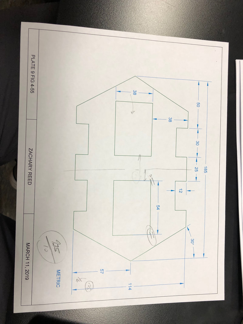
This drawing was our first drawing back on autoCAD, and it was to get our understanding of the tools and functions back. The hardest part about getting back into CAD was the dimensioning and I did make a mistake when dimensioning the cut outs on the object . I took the dimension line from the midpoint of the width rather than the corner and there was no gap the is customary in dimensioning.
|
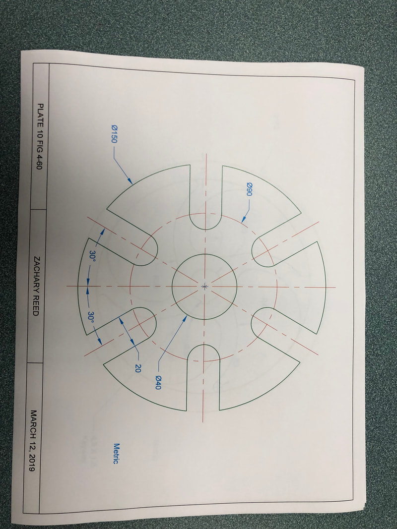
This drawing is of a slotted cam. We made this using autoCAD, and we drew this in metric units. The hard part about drawing this was remembering when use a radius and when to use a diameter to mark a dimension. A big part of this drawing was to use the polar array tool which allowed you to drawm one object and then copy adn revolve them around the chosen axis multiple times.
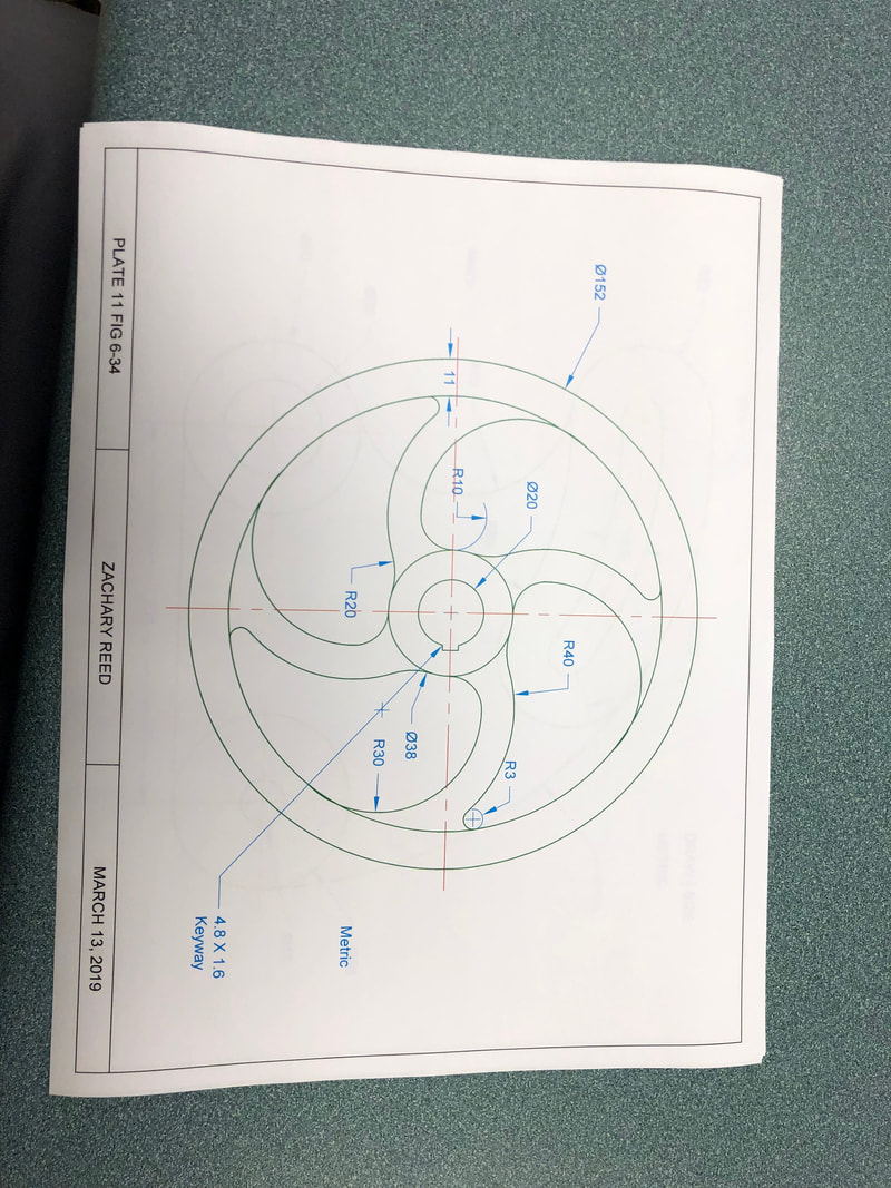
This drawing is a hand wheel and we drew it using autoCAD. This was drawn using metric units. The hard part baout this drawing was putting all of the radius together and having them look like a neat line rather than many lines put together. A big part of this drawing was the offset tool because it allows you to draw the curves that were needed to make the different spokes of the wheel.
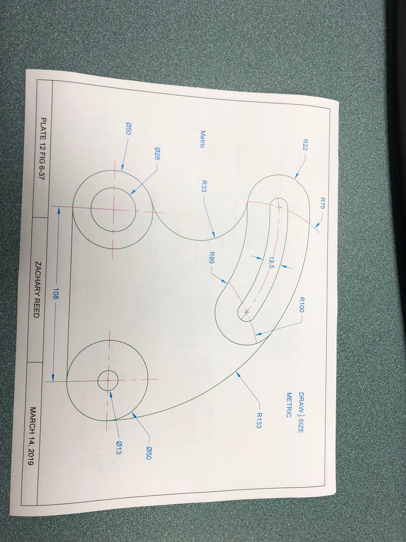
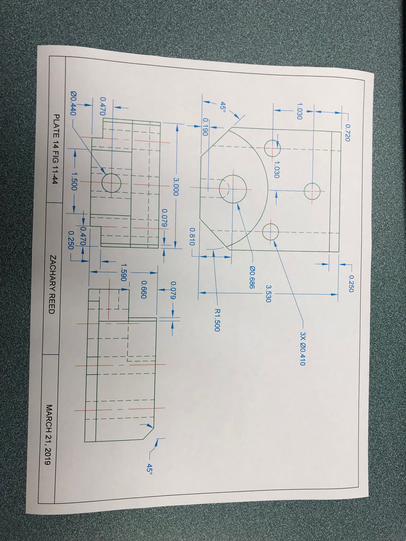
This is a drawing of a lathe quadrant that we made using autoCAD. The made with metric units. This drawing was hard becasue the curves all played off of each other. SO if you did not draw on part right you would have to go back and redo the drawing. A big part of this drawing was the offset tool which allows you to set a distance for a selected line to moved to the left or right.
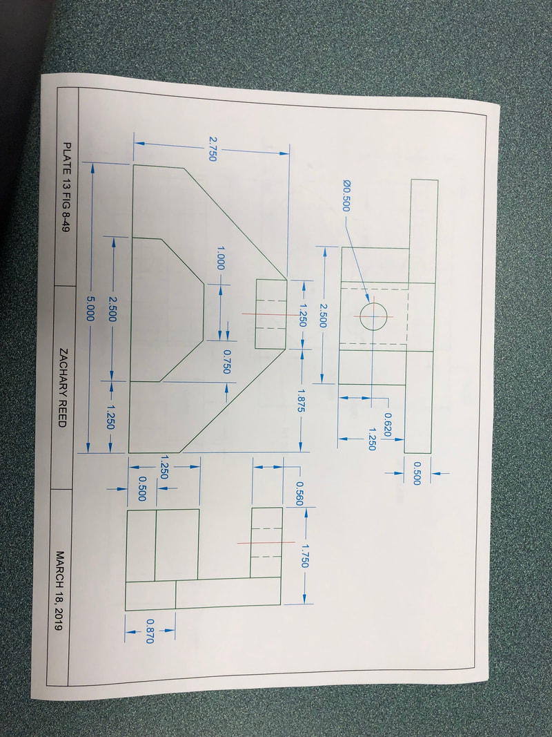
This is an image of a jig block we drew this with autoCAD. This is a orthographic drawing and we had to look at the top, front, and right side of the object to draw it to match the real world object. The hardest part about this drawing was the dimensioning because with the multiple views it was hard to see if you repeated the same length more than once.
This is a drawing of a lock bolt block we drew this using autoCAD. The hard part about this drawing was the angle that is shown best in the top view. Drawing this angle on the right side view is difficult because all the lines and the hidden lines mess with your head and you have to really pay attention to the shape to draw it right. This was also a pictorial drawing so you had to look at the top, front , and right side view.
